
In the challenging world of underground mining, where the earth itself can be both a resource and a formidable adversary, one element stands paramount above all others for the safety and productivity of operations: mine ventilation. Ventilation is the heartbeat of an underground mine. It is the primary control against the most hostile elements of the subsurface environment: heat, gas, and dust. It’s far more than just moving air around; it’s about creating and maintaining a breathable, safe, and comfortable atmosphere deep beneath the surface. Think of it as the mine’s circulatory system, constantly bringing in fresh air and expelling the stale, the hot, and the hazardous.
Why Ventilation is the Mine’s True North Star
For any mining engineer, understanding and mastering ventilation is non-negotiable. It directly impacts the health and well-being of every person working underground, and by extension, the efficiency and profitability of the entire operation. Here’s why it’s so critical:
- Breathing Easy: Ensuring a constant supply of oxygen and diluting harmful gases like methane, carbon monoxide, and the various fumes generated from blasting and diesel equipment. These silent killers are a constant threat, and proper ventilation is the first line of defense.
- Beating the Heat: Deep mines can be incredibly hot, not just from geothermal heat but also from machinery. Effective ventilation helps manage temperature and humidity, preventing heat stress and maintaining comfortable working conditions.
- Directing the Flow: Strategically guiding fresh air to active working faces and efficiently sweeping away contaminated air. It’s a delicate balance, ensuring no dead zones where hazards can accumulate.
- The Right Fan for the Job: Selecting and positioning the right fans – whether axial or centrifugal – is an art and a science. Their placement and power are crucial for moving vast quantities of air effectively.
- Designing the Lungs of the Mine: Planning intricate primary, secondary, and auxiliary ventilation systems. This involves designing airways, installing regulators to control airflow, and building stoppings to direct it precisely where needed.
- Emergency Preparedness: In the face of unforeseen events like fires or explosions, a well-designed ventilation system can be a lifesaver, facilitating rapid evacuation and controlling the spread of smoke and fumes.
Part 1: Mine Air Physics & Psychrometry
Before selecting a fan or digging a shaft, a mining engineer must understand the medium they are moving: Air. In deep mines, air is not a constant fluid; its density changes significantly with depth (pressure) and temperature. This affects fan performance and power costs drastically.
1.1. The Standard Atmosphere
Ventilation manufacturers test fans under “Standard Conditions”. In the field, we must correct these to “Actual Conditions”.
- Standard Air Density ($\rho_{std}$): $1.2 \, \text{kg/m}^3$
- Standard Pressure ($P_{std}$): $101.325 \, \text{kPa}$ (Sea Level)
- Standard Temperature ($T_{std}$): $20^\circ\text{C}$ ($293.15 \, \text{K}$)
- Composition (Dry): $78.09\% \, N_2$, $20.95\% \, O_2$, $0.93\% \, \text{Ar}$, $0.03\% \, CO_2$
1.2. Fundamental Gas Laws
Mine air behaves as a perfect gas mixture. We rely on three laws to predict how it reacts to the mine environment.
Boyle’s Law (Pressure-Volume): At constant temperature, volume is inversely proportional to pressure. If you double the pressure, you halve the volume.
\[P_1 V_1 = P_2 V_2\]Charles’ Law (Temperature-Volume): At constant pressure, volume expands as temperature rises. This expansion drives Natural Ventilation Pressure (NVP).
\[\frac{V_1}{T_1} = \frac{V_2}{T_2}\]The Universal Gas Law: Combines both laws. It states that for a given mass of gas, $PV/T$ is constant.
\[\frac{P_1 V_1}{T_1} = \frac{P_2 V_2}{T_2}\]1.3. Calculating Air Density ($\rho$) in the Field
This is the single most important calculation for fan selection. A fan moving $100 \, m^3/s$ at surface density ($1.2 \, kg/m^3$) moves the same volume but significantly more mass at the bottom of a deep shaft.
A. For Dry Air (Approximation)
If the air is relatively dry, use the simplified formula:
\[\rho = \frac{P}{R \cdot T}\]- $\rho$: Density ($kg/m^3$)
- $P$: Absolute Pressure ($Pa$)
- $R$: Gas Constant for Dry Air ($287.1 \, J/kg\cdot K$)
- $T$: Absolute Temperature (Kelvin $= ^\circ C + 273.15$)
B. For Humid Mine Air (The Precision Method)
Real mine air contains moisture. Since water vapor is lighter than air, humid air is lighter (less dense) than dry air at the same temperature.
To calculate precise density, we use the derived formula:
\[\rho = \frac{P - 0.378e}{0.2871 \cdot (t_d + 273.15)}\]- $P$: Barometric Pressure ($kPa$)
- $e$: Partial pressure of water vapor ($kPa$)
- $t_d$: Dry Bulb Temperature ($^\circ C$)
Calculating Vapor Pressure ($e$):
\[e = e_s - 0.00066 \cdot P \cdot (t_d - t_w)\]Where $e_s$ is the saturated vapor pressure at the wet-bulb temperature ($t_w$).
Field Example:
- Pressure ($P$): $97.5 \, kPa$
- Dry Bulb ($t_d$): $30^\circ C$
- Wet Bulb ($t_w$): $25^\circ C$
Using the formula, the density $\rho$ is calculated to be 1.097 kg/m³.
1.4. Psychrometry & Measurement
In mining, we measure two types of temperature to determine the air’s cooling power and moisture content:
Dry Bulb Temperature ($t_d$): The actual air temperature. It must be measured away from radiant heat sources (like diesel engines).
Wet Bulb Temperature ($t_w$): Measured with a thermometer bulb covered in a wet cotton sleeve. Air must flow over it at $>3 \, m/s$ for accuracy.
Dew Point: If air is cooled, it reaches a temperature where it can no longer hold its water vapor, leading to condensation (fogging). This is the Dew Point.
1.5. Natural Ventilation Pressure (NVP)
NVP occurs when there is a difference in density between the air in the downcast shaft and the air in the upcast shaft.
-
Winter: Cold, dense air flows down the intake naturally, aiding the fans.
-
Summer: Warm, light air in the intake may resist the flow, opposing the fans.
Part 2: Mine Gases, Hazards & Detection Strategies
While airflow physics dictates how we move air, the contaminants dictate how much air we need. A ventilation engineer must essentially be an atmospheric chemist. In the field, you are fighting three enemies: Asphyxiants, Toxins, and Explosives.
2.1. The “Damps”: Mine Gases Lookup Table
Historically, miners grouped gases into “Damps” (from the German Dampf for vapor). In modern engineering, we classify them by specific gravity (SG) relative to air ($SG_{air} \approx 1.0$) to determine where to test for them.
- WA Limits: Based on Work Health and Safety (Mines) Regulations 2022 (Safe Work Australia standards).
- Source Data: Specific Gravities and descriptions derived from lecture notes.
| Gas | Formula | SG (Air=1) | WA TWA (8hr) | WA STEL (15min) |
|---|---|---|---|---|
| Oxygen | $O_2$ | 1.10 | > 19.5% | - |
| Methane | $CH_4$ | 0.55 | - | - |
| Carbon Monoxide | $CO$ | 0.97 | 30 ppm | - |
| Carbon Dioxide | $CO_2$ | 1.53 | 5,000 ppm | 30,000 ppm |
| Hydrogen Sulfide | $H_2S$ | 1.19 | 10 ppm | 15 ppm |
| Nitrogen Dioxide | $NO_2$ | 1.58 | 3 ppm | 5 ppm |
| Hydrogen | $H_2$ | 0.07 | - | - |
| Sulfur Dioxide | $SO_2$ | 2.26 | 2 ppm | 5 ppm |
Critical Notes
- Oxygen: Life Support. <19.5% is oxygen deficiency. <6% leads to rapid loss of consciousness and death.
- Methane (Firedamp): Explosive. Range: 5-15%. Peak violence at ~9.8%. Layers at the roof.
- Carbon Monoxide (Whitedamp): Toxic. Binds to hemoglobin 300x stronger than $O_2$. Colorless/Odorless. Product of fire/diesel.
- Carbon Dioxide (Blackdamp): Asphyxiant. Acid taste. Settles in sumps/floors. Increases breathing rate.
- Hydrogen Sulfide (Stinkdamp): Highly Toxic. Rotten egg smell, but desensitizes nose rapidly (olfactory fatigue).
- Nitrogen Dioxide: Toxic. Reddish-brown. Causes pulmonary edema (fluid in lungs). Common after blasting.
- Hydrogen: Explosive. Wide range (4-74%). Found in battery charging bays. Layers aggressively at the roof.
- Sulfur Dioxide: Toxic. Pungent acid smell. Byproduct of sulphide ore dust explosions or diesel.
Field Rule:
- Head (Roof): Test for Methane ($CH_4$) and Hydrogen ($H_2$).
- Nose (General Body): Test for $CO$, $NO_x$, $O_2$.
- Toes (Floor): Test for $CO_2$, $H_2S$.
2.2. Airborne Dust & Diesel Particulates (DPM)
Dust is not just a nuisance; it is a chronic killer. In WA mining, strict adherence to silica and diesel limits is mandatory.
A. Classification
- Fibrogenic: Causes scar tissue in lungs (e.g., Silica/Quartz $\to$ Silicosis, Asbestos $\to$ Asbestosis).
- Carcinogenic: Causes cancer (e.g., Radon daughters, Diesel Particulate Matter, Arsenic).
- Explosive: Coal dust, sulphide dusts.
- Nuisance: Reduces visibility and irritates eyes (e.g., Limestone).
B. Critical Limits (WA)
- Respirable Crystalline Silica: $0.05 \, mg/m^3$ (TWA). Note: This is strictly enforced.
- Diesel Particulate Matter (DPM): $0.1 \, mg/m^3$ (as Elemental Carbon).
- Respirable Coal Dust: $1.5 \, mg/m^3$ (Standard varies, check site VCP).
- Inhalable Dust: $10 \, mg/m^3$.
C. The “Respirable” Danger Zone
Particles smaller than 5 microns ($5 \mu m$) are invisible to the naked eye and bypass the body’s natural filters (nose/throat), lodging deep in the alveoli.
Measurement: Use Gravimetric Samplers (cyclone pulls air through a filter, filter is weighed) or real-time light-scattering Photometers (Tyndallometers).
2.3. Fire Chemistry & Spontaneous Combustion
Understanding fire chemistry allows an engineer to detect a heating event weeks before smoke appears.
A. The Fire Triangle
Three elements are required: Fuel, Oxygen, and Heat.
- Direct Fire Fighting: Removes Heat (water) or Oxygen (foam/extinguishers).
- Sealing: Cuts off Oxygen. Seals in gassy mines must be explosion-proof (rated to withstand overpressure).
B. Spontaneous Combustion (“Spon Com”)
Coal and sulphide ores naturally oxidize. If airflow is “sluggish” (enough to supply $O_2$ but too slow to carry away heat), the rock temperature rises until it auto-ignites.
Detection: Graham’s Ratio ($ICO$)
This is the gold standard for early detection. It measures the efficiency of oxygen consumption.
\[ICO = \frac{CO \text{ produced}}{O_2 \text{ consumed}} = \frac{CO \%}{0.265 \cdot N_2 \% - O_2 \%} \times 100\]- Normal: $< 0.5$ (typically).
- Heating suspected: $> 0.5$ rising to $1.0$.
- Active Fire: $> 2.0$.
C. Explosion Dynamics: The Coward Triangle
Explosions require a specific mixture of gas and oxygen.
-
Methane Explosive Range: 5% (LEL) to 15% (UEL).
-
The “Nose” of the Curve: As oxygen decreases, the explosive range of methane shrinks. Below ~12% Oxygen, a methane explosion is impossible regardless of methane concentration.
-
Coal Dust: A small methane “pop” often raises coal dust into the air, which then ignites, causing the devastating secondary explosion that travels through the mine. Stone dusting (adding inert limestone dust) prevents this propagation.
2.4. Field Checklist for Gas/Dust Control
Re-entry: Never enter a heading after blasting until the ventilation has cleared the “fume” ($NO_x$/$CO$).
Auxiliary Fans: Ensure the ducting is close enough to the face to capture dust (exhausting) or dilute gas (forcing).
Diesel Maintenance: High DPM readings often indicate poor engine maintenance or clogged scrubbers, not just poor airflow.
Bleeder Roads: In longwall mining, ensure bleeder roads are open to drain methane from the goaf (gob) away from the face.
Part 3: Ventilation Systems, Circuits & Network Analysis
Once we understand the air’s properties and the contaminants we need to dilute, the next challenge is distribution. How do we push air through kilometers of rough rock tunnels efficiently?
This section covers the fluid mechanics of ventilation, circuit design, and the mathematical laws that govern airflow distribution.
3.1. The Fundamental Law: Atkinson’s Equation
In electrical engineering, Ohm’s Law ($V=IR$) is the foundation. In mine ventilation, the equivalent is the Square Law (often attributed to J.J. Atkinson). It states that the pressure required to move air is proportional to the square of the quantity.
\[P = R \times Q^2\]Where:
- $P$: Frictional Pressure Drop (Pascals, $Pa$)
- $R$: Aerodynamic Resistance ($Ns^2/m^8$ or “Gauls”)
- $Q$: Airflow Quantity ($m^3/s$)
Calculating Resistance ($R$)
Resistance is a physical property of the airway, independent of the airflow (in fully developed turbulent flow). It is calculated using the physical dimensions of the tunnel:
\[R = \frac{k \cdot L \cdot Per}{A^3}\]- $k$: Friction Factor ($kg/m^3$ or $Ns^2/m^4$) – A coefficient representing the roughness of the airway walls.
- $L$: Length of the airway ($m$).
- $Per$: Perimeter of the airway ($m$) – The “rubbing surface”.
- $A$: Cross-sectional Area ($m^2$).
Field Insight: Notice that Area ($A$) is cubed in the denominator. This means a small increase in tunnel size results in a massive reduction in resistance.
- Doubling the area reduces resistance by a factor of ~8 (depending on perimeter changes).
- Lower resistance = Lower pressure required = Massive power cost savings.
3.2. Shock Losses ($X$)
Friction isn’t the only thief of energy. Whenever airflow changes direction (bends) or changes area (expansions/contractions), flow separation occurs, creating Shock Losses.
In network analysis, shock losses are either added as an “Equivalent Length” to the friction calculation or calculated as velocity pressure heads ($P_v$):
\[P_{shock} = X \cdot P_v\](Where $X$ is a shock factor based on the geometry of the bend/junction).
3.3. Basic Ventilation Circuits
Just like electrical circuits, mine airways are arranged in Series or Parallel. Understanding the difference is critical for fan placement and regulation.
A. Series Circuits
Air flows through one airway, then the next.
- Airflow ($Q$): Constant throughout all branches. ($Q_{total} = Q_1 = Q_2$).
- Pressure ($P$): Cumulative. ($P_{total} = P_1 + P_2 + P_3$).
- Resistance ($R$): Cumulative. ($R_{eq} = R_1 + R_2 + R_3$).
Warning: Series circuits have high resistance. Avoid putting high-volume airways in series if possible, as the fan pressure required will skyrocket.
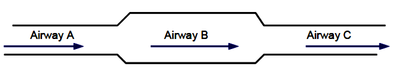
B. Parallel Circuits
The airflow splits at a node, travels through multiple branches, and rejoins.
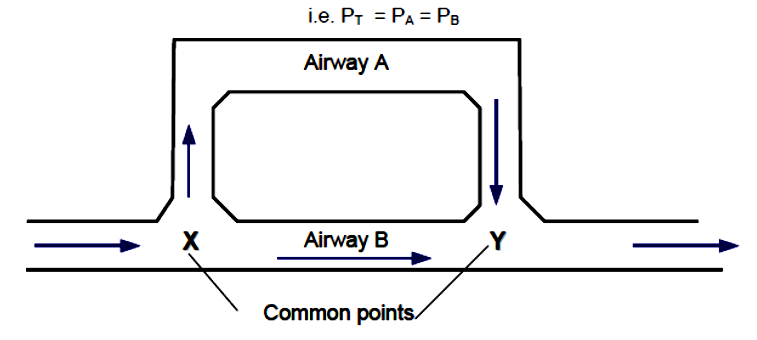
- Pressure ($P$): The pressure drop across all parallel branches is equal. ($P_1 = P_2$).
- Airflow ($Q$): Splits naturally. The path of least resistance gets the most air. ($Q_{total} = Q_1 + Q_2$).
- Equivalent Resistance: The total resistance decreases as you add more parallel paths.
\(\frac{1}{\sqrt{R_{eq}}} = \frac{1}{\sqrt{R_1}} + \frac{1}{\sqrt{R_2}} + \dots\).
3.4. The Equivalent Orifice ($A_{eq}$)
How do you compare the “tightness” of two different mines? We use the Equivalent Orifice. It represents the area of a sharp-edged hole in a thin plate that would offer the same resistance as the entire mine.
\(A_{eq} \approx 0.38 \frac{Q}{\sqrt{P}}\) (Note: The constant 0.38 is derived when P is in $kg/m^2$ or mmWG. In metric SI units with Pascals, standard approximations are often used).
Mine Classification based on $A_{eq}$:
- $< 1 \, m^2$: Narrow/Tight Mine (High Resistance – Requires high pressure fans).
- $1 - 2 \, m^2$: Moderate Mine.
- $> 2 \, m^2$: Wide/Open Mine (Low Resistance – Efficient ventilation).
3.5. Network Analysis: Kirchhoff’s Laws
When circuits become complex (meshes), we use Kirchhoff’s laws to balance the network, exactly as is done in electrical grids.
Kirchhoff’s 1st Law (Junctions): The algebraic sum of air quantities at any junction is zero.
\[\sum Q_{in} = \sum Q_{out}\](Mass is conserved; air doesn’t disappear).
Kirchhoff’s 2nd Law (Meshes): The algebraic sum of pressure drops around any closed loop (mesh) is zero.
\[\sum P = 0\](Or, the sum of pressure drops equals the pressure added by the fan in that mesh).
The Hardy Cross Method:
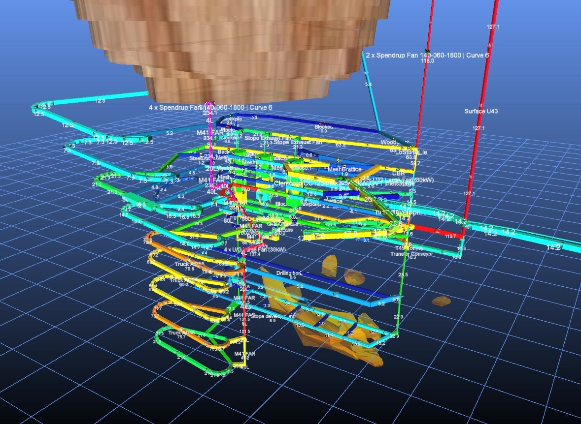
Solving these equations manually for a large mine is impossible. We use the Hardy Cross iterative numerical method. This is the mathematical engine behind software like Ventsim or Deswik.Vent. It guesses an airflow, calculates the error based on Kirchhoff’s laws, applies a correction, and repeats until the error is zero.
3.6. Regulator & Booster Fan Strategies
-
Regulators (Passive): Artificial resistance (like a sliding door) added to a low-resistance branch in a parallel circuit. It forces air into the other (higher resistance) branch to balance flows.
-
Booster Fans (Active): Adds pressure to a specific branch to overcome high resistance without raising the main fan pressure for the whole mine.
Part 4: Mechanical Ventilation & System Design
In modern mining, we cannot rely on Natural Ventilation Pressure (NVP) alone. It is unreliable and often insufficient. We need mechanical energy to overcome the friction and shock losses we calculated in Part 3. This section details the engineering of fans and the design of primary and auxiliary systems.
4.1. Fan Engineering: The Heart of the System
Fans convert rotational mechanical energy into aerodynamic energy (pressure and airflow). In mining, we primarily use two types:
A. Axial Flow Fans
- Mechanism: Air passes through the fan parallel to the shaft. The impeller blades act like an aircraft propeller.
- Characteristics: High volume, relatively lower pressure capabilities compared to centrifugal.
- Application: Most main surface fans and auxiliary booster fans.
- Advantage: Can be made reversible (critical for emergency fire procedures) and usually have adjustable blade pitches to vary performance.
B. Centrifugal (Radial) Fans
- Mechanism: Air enters axially but is discharged radially (90 degrees) by centrifugal force.
- Characteristics: Can generate very high pressures. Rugged and quieter.
- Application: High-resistance mines, scrubber fans, or forcing auxiliary fans with long duct runs.
4.2. The Fan Laws (Affinity Laws)
These are the most useful formulas for a field engineer. They predict how a fan’s performance changes when you alter its rotational speed (RPM) or the air density.
Scenario: You have a fan running at Speed $N_1$. You change the sheaves/VSD to run at $N_2$.
Quantity Law (Linear):
\[\frac{Q_2}{Q_1} = \frac{N_2}{N_1}\]Example: Increase speed by 10% $\to$ Airflow increases by 10%.
Pressure Law (Square):
\[\frac{P_2}{P_1} = \left(\frac{N_2}{N_1}\right)^2\]Example: Increase speed by 10% $\to$ Pressure increases by 21%.
Power Law (Cubic):
\[\frac{W_2}{W_1} = \left(\frac{N_2}{N_1}\right)^3\]Example: Increase speed by 10% $\to$ Power consumption increases by 33%.
Field Warning: Be extremely careful when increasing fan speed. A small gain in airflow ($Q$) results in a massive spike in power ($W$) and mechanical stress. You can easily overload a motor or shatter a shaft if you ignore the Cubic Law.
4.3. Fan Characteristic Curves & Operation
A fan does not have a single “pressure”. It has a Characteristic Curve (Pressure vs. Quantity). The fan will operate only at the point where this curve intersects the Mine System Resistance Curve ($P = R Q^2$).
- The Operating Point: The unique combination of $P$ and $Q$ where the fan capability matches the mine’s demand.
- Stall Zone: The unstable area on the left side of the fan curve (dip). Operating here causes aerodynamic stall (like an airplane), severe vibration, and potential catastrophic failure. Always operate on the steep, right-hand side of the curve.
Fan Efficiency ($\eta$):
\[Air Power (kW) = \frac{Q (m^3/s) \times P (Pa)}{1000}\] \[\eta = \frac{Air Power}{Shaft Power (Input)}\]Efficient fans save millions in electricity over the life of a mine.
4.4. Primary Ventilation Systems
How do we arrange the main airways?
U-Tube System:
- Air flows towards the workings and returns via a parallel airway separated by stoppings.
- Common in: Room and pillar, advancing longwalls.
- Risk: High leakage through the gob/waste area; difficult to control spontaneous combustion.
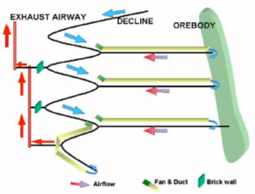
Through-Flow System:
- Intake and Return shafts are geographically separated (e.g., Intake at one end of the lease, Exhaust at the other).
- Common in: Modern metalliferous mines, retreat mining.
- Benefit: Reduces leakage paths, lowers overall resistance, and separates transport from return air.
4.5. Auxiliary Ventilation (Development Headings)
When driving a dead-end heading (blind heading), the main airflow passes by the entrance. We must use ducts and fans to force air into the face.
A. Forcing System
- Setup: Fan is in the fresh airway, pushing air through flexible (layflat) duct to the face.
- Pros: Delivers high-velocity cool air directly to the face; effective at sweeping heavy gases ($CO_2$) and diluting methane. Cheaper ducting.
- Cons: Dust and fumes travel back over the operator/machine in the heading.
B. Exhausting System
- Setup: Fan sucks air from the face through rigid (spiral/wire-reinforced) duct.
- Pros: Captures dust and fumes at the source; fresh air enters via the drive, keeping the operator in clean air.
- Cons: Requires expensive rigid ducting (to prevent collapse under negative pressure); poor at scouring the face for gas; creates dead zones at the face corners.
C. Overlap System (The Hybrid)
- Setup: Uses a primary duct (usually forcing) to bring air near the face, and a smaller secondary fan (exhausting with a dust scrubber) mounted on the miner/header to clean the air.
- Goal: Combines the cooling/dilution of forcing with the dust control of exhausting.
Field Rule for Ducts:
- Leakage: A 100m duct with poor joints can lose >50% of its air. Good maintenance is vital.
- Distance: The duct outlet should be within 20-30m of the face (forcing) to ensure scour velocity, but check local WA regulations for specific limits.
Part 5: Ventilation Control Devices & Emergency Management
The best fans and perfect calculations mean nothing if the air doesn’t go where it’s needed. In the field, we use Ventilation Control Devices (VCDs) to direct airflow. Furthermore, when things go wrong (fire or explosion), the integrity of these devices becomes the difference between a minor incident and a catastrophe.
5.1. Ventilation Control Devices (VCDs)
These are the physical structures used to manage the airflow network.
A. Stoppings (Permanent Seals)
Walls built to separate intake airways from return airways to prevent short-circuiting.
- Construction: Concrete blocks, masonry, or monolithic pumped cement.
- Field Note: Leaking stoppings are the #1 cause of low volumetric efficiency. If air leaks through a stopping, you are paying electricity to recirculate air that never reaches the face.
B. Ventilation Doors & Airlocks
Used where men or machinery must travel between intake and return.
- Airlock: Two doors in series. Rule #1: Never open both doors at the same time. This creates a direct short circuit, potentially stalling the main fan or reversing airflow in other parts of the mine.
- Pressure Direction: Doors should always open towards the higher pressure so that the air pressure helps keep them sealed.
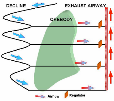
C. Regulators
An artificial restriction (usually a sliding door in a stopping) used to reduce flow in a low-resistance branch (e.g., a split close to the shaft bottom) to force air to higher-resistance branches deeper in the mine.
D. Air Crossings (Overcasts/Undercasts)
Structures that allow intake and return airways to cross each other without mixing.
- Construction: Steel ducts or concrete bridges.
- Risk: A leakage here reinjects exhaust gas directly into the fresh air stream. They must be robust and well-sealed.
5.2. Emergency Sealing Strategies
When a fire cannot be extinguished directly (e.g., a goaf fire or deep-seated spontaneous combustion), the area must be sealed to cut off the oxygen supply.
A. Explosion-Proof Seals
In gassy mines (coal/methane), there is a danger that sealing a fire will create an explosive gas mixture behind the seal before the oxygen drops below 12% (The Coward Triangle “Nose”). Therefore, seals must be built to withstand the overpressure of an explosion.
- Rating: Typically designed to withstand 140 kPa (20 psi) to 345 kPa (50 psi) depending on local regulations (e.g., WA Mines Safety standards).
- Construction: Two bulkheads 5-10m apart, filled with sand, fly ash, or pumped gypsum.
B. Sampling Behind Seals
You cannot manage what you cannot see. Seals must be fitted with sampling pipes to monitor the atmosphere inside.
- Design: The pipe should extend at least 30 meters inby (into the sealed area) to avoid sampling “breathing” air near the wall.
- Stratification: Ideally, sample from the roof (methane), floor ($CO_2$), and middle for a representative analysis.
5.3. Explosion Suppression (Barriers)
In coal mines, a small methane explosion can lift coal dust into the air, triggering a massive secondary dust explosion that propagates through the mine. Barriers are designed to stop this flame front.
A. Stone Dust Barriers
Shelves loaded with inert limestone dust. The shockwave of the explosion tips the shelves, creating a cloud of inert dust that absorbs the heat and quenches the flame before it arrives.
B. Water Barriers
Troughs filled with water suspended from the roof. The shockwave shatters the troughs, creating a dense water curtain that cools the flame.
5.4. Managing Spontaneous Combustion (“Spon Com”)
Prevention is better than cure. Once a heating starts in a goaf, it is incredibly difficult to stop.
- Prevention: Minimize leakage! Air flowing slowly through broken coal provides oxygen for oxidation but doesn’t remove the heat.
- Pressure Balancing: Adjusting regulators to equalize the pressure across a goaf area so that no air flows through it.
- Grouting: Injecting sealants into pillar cracks to stop oxygen ingress.
5.5. Routine Management ( The Ventilation Officer)
In Western Australia, the Ventilation Officer (VO) is a statutory position. Routine duties include:
Pressure/Quantity Surveys: Measuring $P$ and $Q$ to calculate Resistance ($R$) and update the network model.
Gas Monitoring: Calibration of detectors and recording trends.
Fan Testing: Checking operating points against the fan curve.
VCP Maintenance: Updating the Ventilation Control Plan as the mine develops.
The Engineer’s Responsibility
Mine ventilation is a complex discipline that merges fluid mechanics, thermodynamics, chemistry, and emergency management. Whether you are calculating the Equivalent Orifice to benchmark your mine’s resistance or rushing to interpret gas samples behind a seal during a crisis, the fundamental physics remain the same.
As a mining engineer, your calculations do more than just satisfy a spreadsheet—they ensure that every miner returns home safely at the end of the shift.
Note: This handbook aggregates global mining theory with specific focus on standards relevant to modern mechanized mining. Always refer to your site-specific Ventilation Control Plan (VCP) and local regulations.
Bonus: Python Code Example
import numpy as np
import matplotlib.pyplot as plt

def get_user_input():
    """
    Prompts the user to enter coefficients for the mine and fan characteristics.
    Includes error handling to ensure valid numerical input.
    """
    print("--- Mine Ventilation Operating Point Calculator ---")
    print("\nThis script calculates the operating point where the fan curve intersects the mine curve.")

    while True:
        try:
            # 1. Mine Characteristic Curve Input: H_mine = R * Q^2
            print("\nStep 1: Enter Mine Characteristics")
            print("The Mine Characteristic Curve is defined as H = R * Q^2")
            mine_resistance = float(input("Enter the total mine resistance (R) in Ns²/m⁸ (e.g., 0.05): "))
            if mine_resistance <= 0:
                print("Error: Mine resistance must be a positive number.")
                continue

            # 2. Fan Characteristic Curve Input: H_fan = A - B*Q - C*Q^2
            print("\nStep 2: Enter Fan Characteristics")
            print("The Fan Characteristic Curve is approximated by H = A - B*Q - C*Q^2")
            fan_a = float(input("Enter the 'A' coefficient (shut-off pressure in Pa, e.g., 800): "))
            fan_b = float(input("Enter the 'B' coefficient (e.g., 0.1): "))
            fan_c = float(input("Enter the 'C' coefficient (e.g., 0.003): "))

            if fan_a <= 0:
                print("Error: Fan coefficient 'A' (shut-off pressure) must be positive.")
                continue

            return mine_resistance, fan_a, fan_b, fan_c

        except ValueError:
            print("\nInvalid input. Please enter valid numbers only. Let's try again.")


def calculate_operating_point(R_mine, A_fan, B_fan, C_fan):
    """
    Calculates the operating point by solving for the intersection of the two curves.
    H_mine = H_fan  =>  R*Q^2 = A - B*Q - C*Q^2
    This rearranges to a standard quadratic equation: (R + C)*Q^2 + B*Q - A = 0
    """
    # Coefficients for the quadratic equation ax^2 + bx + c = 0
    a = R_mine + C_fan
    b = B_fan
    c = -A_fan

    # Using the quadratic formula to solve for Q (airflow)
    # Q = (-b ± sqrt(b^2 - 4ac)) / 2a
    # We take the positive root as airflow cannot be negative.
    discriminant = b**2 - 4*a*c
    if discriminant < 0:
        print("\nError: No real solution exists. The fan may be too weak for the mine system.")
        return None, None

    q_op = (-b + np.sqrt(discriminant)) / (2 * a)

    # Calculate the operating pressure using the mine curve
    h_op = R_mine * (q_op**2)

    return q_op, h_op


def plot_curves(R_mine, A_fan, B_fan, C_fan, q_op, h_op):
    """
    Generates and displays a plot of the mine and fan characteristic curves,
    highlighting the operating point.
    """
    # Generate a range of airflow values for plotting
    # We will plot from Q=0 to 1.5 times the operating airflow to see the full curves
    q_max_plot = q_op * 1.5
    q_values = np.linspace(0, q_max_plot, 400)

    # Calculate H for each Q for both curves
    h_mine_values = R_mine * (q_values**2)
    h_fan_values = A_fan - B_fan*q_values - C_fan*(q_values**2)
    # Ensure fan pressure doesn't go below zero for the plot
    h_fan_values[h_fan_values < 0] = 0

    # Plotting
    plt.figure(figsize=(12, 8))

    # Plot the curves
    plt.plot(q_values, h_mine_values, label='Mine Characteristic Curve ($H = R \cdot Q^2$)', color='blue', linewidth=2)
    plt.plot(q_values, h_fan_values, label='Fan Characteristic Curve ($H = A - BQ - CQ^2$)', color='green', linewidth=2)

    # Plot the operating point
    plt.plot(q_op, h_op, 'ro', markersize=10, label=f'Operating Point\nQ = {q_op:.2f} m³/s\nH = {h_op:.2f} Pa')

    # Add lines from the point to the axes
    plt.vlines(q_op, 0, h_op, colors='r', linestyles='--')
    plt.hlines(h_op, 0, q_op, colors='r', linestyles='--')

    # Formatting the plot
    plt.title('Mine & Fan Characteristic Curves', fontsize=16)
    plt.xlabel('Airflow (Q) [$m^3/s$]', fontsize=12)
    plt.ylabel('Pressure (H) [Pa]', fontsize=12)
    plt.legend(fontsize=10)
    plt.grid(True, which='both', linestyle='--', linewidth=0.5)
    plt.xlim(left=0)
    plt.ylim(bottom=0)

    # Show the plot
    plt.show()


def main():
    """Main function to run the script."""
    R_mine, A_fan, B_fan, C_fan = get_user_input()

    q_op, h_op = calculate_operating_point(R_mine, A_fan, B_fan, C_fan)

    if q_op is not None and h_op is not None:
        print("\n--- Calculation Results ---")
        print(f"Operating Airflow (Q): {q_op:.2f} m³/s")
        print(f"Operating Pressure (H): {h_op:.2f} Pa")
        print("\nGenerating plot...")
        plot_curves(R_mine, A_fan, B_fan, C_fan, q_op, h_op)

if __name__ == "__main__":
    main()